
Views: 256 Author: shandong Allstar Grinding Ball Publish Time: 2026-08-10 Origin: Site


Content Menu
● How a Grinding Mill Diagram Explains Grinding Action
● The Main Parts of a Ball Mill Diagram
>> Mill Shell, Liners, and Lifter Bars
● Forged Steel Balls, Cast Steel Balls, Rods, and Cylpebs
● A Practical Method for Reading a Mill Diagram
● Common Mill Diagram Mistakes That Raise Grinding Costs
>> Choosing Media by Diameter Alone
>> Ignoring Media Size Distribution
>> Treating Breakage as Normal
>> Separating Media Decisions From Mill Conditions
● Why OEM Buyers Work With SHANDONG ALLSTAR
● FAQ About Mill Diagrams and Grinding Media
>> What is the purpose of a mill diagram?
>> How does a ball mill diagram help select grinding balls?
>> What is the difference between forged and cast grinding balls?
>> Why do grinding balls break inside a mill?
>> How often should a grinding-media charge be checked?
>> Can SHANDONG ALLSTAR provide OEM grinding media?
A clear mill diagram is more than a technical drawing. For mining, cement, and power-generation operators, it is a practical map of how material, energy, liners, and grinding media work together inside a mill. At SHANDONG ALLSTAR GRINDING BALL CO., LTD., we use mill diagrams as the starting point for recommending forged grinding balls, cast grinding balls, grinding rods, and grinding cylpebs that fit the real operating conditions of each customer.
A well-read grinding mill diagram helps purchasing teams and plant engineers move beyond buying media by diameter or price alone. It connects mill type, feed size, liner design, rotation speed, slurry conditions, discharge method, and media selection. That connection matters because the wrong media can increase consumption, reduce throughput, create irregular wear, and raise the cost per ton of finished product.
As a global manufacturer serving mining, cement, and power-industry customers, SHANDONG ALLSTAR provides OEM grinding media solutions for overseas brands, wholesalers, and industrial manufacturers. Our role is not simply to supply steel balls. Our goal is to help customers interpret the mill system, define the right media specification, and build a more consistent grinding-media supply program.
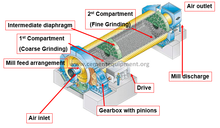
A mill diagram is a visual representation of a grinding mill and its key operating components. It may be a simple cross-section, an engineering drawing, a process-flow diagram, or a detailed mill-charge illustration. For procurement teams, it explains where the grinding media works. For engineers, it provides context for evaluating grinding efficiency, wear behavior, and maintenance risk.
In a typical ball mill diagram, material enters through the feed end, moves through a rotating cylindrical shell, interacts with grinding media, and exits through an overflow or grate-discharge system. As the shell rotates, the grinding balls are lifted by the liners and then fall or cascade through the material. The resulting impact and abrasion reduce particle size.
A useful mill diagram should identify:
- Feed end: Where ore, clinker, coal, or other raw material enters the mill
- Mill shell: The rotating body that contains the charge
- Mill liners and lifters: Components that protect the shell and influence media motion
- Grinding media: Balls, rods, or cylpebs that deliver impact and abrasion
- Charge level: The combined volume of media, material, and slurry inside the mill
- Discharge system: The route through which ground material leaves the mill
- Drive system: Motor, gearbox, pinion, girth gear, and associated controls
Understanding these elements makes a mill diagram a commercial tool as well as an engineering tool. It helps buyers ask better questions before ordering grinding media.
The central purpose of a mill diagram is to show how internal motion creates grinding. In a rotating mill, the liners carry the grinding media upward. At a certain point, gravity overcomes the lifting force and the media moves downward through the charge.
This motion is generally described in three ways:
| Media motion | What happens inside the mill | Typical grinding effect |
|---|---|---|
| Cascading | Media rolls and slides down the charge surface | Abrasion and finer-particle grinding |
| Cataracting | Media is lifted and thrown through the mill charge | Higher impact for coarser particles |
| Centrifuging | Media remains pinned to the shell | Poor grinding; usually an undesirable condition |
The best operating condition is not always the highest-impact condition. The ideal media trajectory depends on feed size, ore hardness, mill speed, liner profile, slurry density, and target product size. A grinding mill diagram should therefore be read together with operating data, not as an isolated illustration.
For example, a customer processing coarse mineral feed may require larger forged steel balls to generate sufficient impact energy. A cement mill working on finer-stage grinding may benefit from a carefully balanced mix of smaller grinding balls or grinding cylpebs, depending on the mill design and separator performance.
The feed system controls how material enters the mill. In a mill diagram, the feed end is usually shown at the inlet trunnion, chute, or feed spout. This area affects throughput, material distribution, and wear patterns near the first chamber.
Feed size is one of the most important inputs for grinding-media selection. Large feed particles generally need larger media to create adequate breakage force. However, media that is too large can reduce the number of contact points available for fine grinding. The correct approach is to balance impact capability and surface-area efficiency.
Before requesting a quotation, buyers should provide:
- Maximum and average feed size
- Material hardness and abrasiveness
- Moisture content or slurry characteristics
- Required product fineness
- Mill dimensions and effective grinding length
- Current media size distribution
- Average media consumption and operating hours
The shell contains the grinding charge, but the liners shape the grinding action. A mill diagram should show whether the liner system is designed for lifting, cascading, impact, or a combination of these motions.
Liners wear over time. As lifter height and profile change, the trajectory of grinding balls also changes. That means a media program that performed well with new liners may require adjustment later in the liner campaign. Experienced operators monitor media condition, liner condition, mill speed, and throughput as connected variables rather than treating each item separately.
For this reason, SHANDONG ALLSTAR encourages customers to evaluate grinding media together with liner condition and operating goals. Media quality should support stable mill performance, not merely meet a nominal hardness requirement.
The grinding-media charge is the working mass inside the mill. Depending on the equipment and process, it may include forged steel balls, cast grinding balls, grinding rods, or grinding cylpebs.
A mill diagram can reveal several important media-selection factors:
- Whether the mill needs high-impact breakage or fine abrasion grinding
- Whether a single ball size or a graded ball charge is more appropriate
- Whether the first and second chambers require different media sizes
- Whether the discharge design is sensitive to broken or misshapen media
- Whether media density, hardness, and wear profile match the application
A media charge is not static. As balls wear, their diameter declines and the size distribution changes. Regular top-up practices are essential to maintain the intended grinding environment.
The discharge end determines how ground material leaves the mill. Common designs include overflow discharge and grate discharge. The diagram may also show diaphragms, screens, pulp lifters, or separators.
A worn or poorly selected grinding medium can affect this zone. Broken balls, irregular shapes, excessive fines, or unsuitable media size may disrupt flow and consume useful mill volume. Therefore, a reliable supplier should consider the entire circuit, including the discharge arrangement, before finalizing a media recommendation.
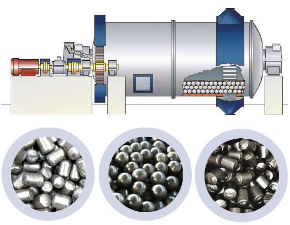
The right grinding media depends on the application—not on a single universal rule. At SHANDONG ALLSTAR, we manufacture a broad range of grinding media for mining, cement, and power applications, including forged grinding balls, cast grinding balls, grinding rods, and grinding cylpebs.
| Grinding media | Typical strength | Common applications | Selection consideration |
|---|---|---|---|
| Forged steel balls | Strong impact resistance and dependable toughness | Mining SAG mills and ball mills, coarse grinding | Often preferred where impact loading is high |
| Cast grinding balls | Wear-resistant alloy options | Ball milling and certain cement or mineral applications | Chemistry, hardness profile, and breakage resistance should be verified |
| Grinding rods | Line-contact grinding action | Rod mills and selected coarse-grinding circuits | Straightness and resistance to tangling are important |
| Grinding cylpebs | Higher surface area for fine grinding | Cement mills and fine-grinding stages | Often evaluated for finish-grinding efficiency and size distribution |
The most suitable option should be confirmed through operating data, product testing, and, where appropriate, a controlled trial. A purchasing decision based only on unit price can overlook important cost drivers such as wear rate, breakage, throughput stability, and the labor required for media handling.
A mill diagram becomes much more valuable when it is used as part of a structured review. We recommend the following process before specifying or changing grinding media.
1. Identify the mill type. Confirm whether the system is a ball mill, rod mill, SAG mill, cement mill, or another grinding configuration.
2. Map the material flow. Follow the route from feed entry to discharge. Note chambers, diaphragms, separators, screens, and recirculation loops.
3. Review the mill dimensions. Record shell diameter, effective length, chamber layout, and available grinding volume.
4. Check liner condition. Observe lifter wear, liner profile, exposed bolts, and areas of uneven wear. These details can explain unexpected media behavior.
5. Define the media objective. Is the primary requirement coarse-particle impact, fine-particle abrasion, lower wear consumption, or improved product consistency?
6. Document operating conditions. Gather feed size, throughput, mill speed, power draw, slurry density, product size, and current media consumption.
7. Select a trial specification. Choose media type, diameter range, hardness, alloy design, and top-up schedule based on the full operating picture.
8. Measure commercial results. Compare media consumption, output, product fineness, downtime, and total grinding cost—not just purchase price.
This method is especially useful for OEM customers, distributors, and overseas brands that need a repeatable process for serving different end-user mills.
Common Mill Diagram Mistakes That Raise Grinding Costs
Many organizations have drawings of their mills but do not use them fully in the media-selection process. The following mistakes are common.
Ball diameter is important, but it is only one variable. Material competency, feed size, mill speed, liner design, and target fineness all affect the correct selection. A ball that is ideal for one mine or cement plant may be inefficient in another.
A mill charge often performs best with a planned mix of sizes rather than one nominal diameter. Over time, wear changes the charge profile. If top-up additions do not restore the intended balance, grinding performance can decline gradually without an obvious mechanical failure.
Broken or severely misshapen media should be investigated, not accepted as routine. It can indicate that the media does not match the impact environment, that heat treatment or material properties need review, or that the mill is operating outside the intended conditions.
Grinding media, liners, speed, feed properties, and discharge behavior are interconnected. When production changes, the original media specification should be reviewed rather than assumed to remain optimal.
For an overseas brand, wholesaler, or industrial manufacturer, an OEM grinding-media supplier must provide more than production capacity. The supplier must understand specification control, consistency, packaging requirements, documentation, and long-term communication.
SHANDONG ALLSTAR GRINDING BALL CO., LTD. positions grinding media as a performance component within the customer's mill system. We support OEM partners with product options for different grinding applications, including forged and cast steel balls, rods, and cylpebs.
Our OEM-oriented approach can include:
- Custom specifications based on mill and material conditions
- Product selection support for mining, cement, and power applications
- Private-label and customer-branding cooperation
- Packaging options designed for export handling and distribution
- Batch consistency and quality-control documentation requirements
- Communication focused on long-term supply stability
Customer Validation: Add verified customer testimonials here only after obtaining written approval. Strong testimonials should state the application, product type, measurable result, customer role, and permission to publish. Avoid anonymous or unsubstantiated claims such as "best grinding balls" or "lowest cost."
A mill diagram shows the structure and material flow of a grinding mill. It helps engineers and buyers understand where grinding media works and what operational factors influence grinding performance.
It identifies the mill type, feed and discharge arrangement, chamber layout, liner design, and grinding environment. These details help determine the appropriate media type, diameter range, and top-up strategy.
Forged grinding balls are commonly selected for high-impact environments because of their toughness and impact resistance. Cast grinding balls can offer strong wear resistance in suitable applications, but the correct alloy and quality controls must match the operating conditions.
Possible causes include unsuitable media chemistry or heat treatment, excessive impact conditions, poor liner-media-speed interaction, tramp material, or operating conditions that differ from the original design assumptions.
The frequency should reflect the application's wear rate, production targets, and maintenance schedule. High-throughput or highly abrasive circuits generally require more frequent monitoring of media size distribution, consumption, and breakage.
Yes. SHANDONG ALLSTAR GRINDING BALL CO., LTD. provides OEM cooperation for overseas brands, wholesalers, and manufacturers requiring forged steel balls, cast steel balls, grinding rods, and grinding cylpebs for industrial grinding applications.
1. ScienceDirect. [Ball Mill: Overview, Structure, and Operating Principle]. [sciencedirect]
2. Metso. [Questions and Answers on Grinding Technology]. [metso]
3. Metso. [Correct Liner Selection and Optimal Mill Efficiency]. [metso]
4. AusIMM. [The Selection, Design and Application of Mill Liners for Large Wet Grinding Mills]. [ausimm]
5. AusIMM. [Forging Ahead: Improving Plant Performance Through Grinding Media Optimisation]. [ausimm]
6. FLS. [Tower Mill Fine-Grinding Technology Overview]. [video.flsmidth]
Hot Tags: China, Global, OEM, private label, manufacturers, factory, suppliers, manufacturing company


