
Views: 249 Author: Site Editor Publish Time: 2026-08-14 Origin: Site


Content Menu
● What Is a Ball Mill Liner Wear Chart?
● How to Read a Ball Mill Liner Wear Chart Step by Step
>> 1. Confirm the Baseline Measurement
>> 2. Identify the Measurement Location
>> 4. Calculate the Liner Wear Rate
>> 5. Compare Remaining Thickness With the Minimum Limit
● Ball Mill Liner Wear Chart Example
● How to Interpret Common Liner Wear Patterns
>> Uniform Wear Across the Shell
>> Excessive Wear at the Discharge End
>> Localized Grooves, Holes, Cracks, or Broken Plates
● What Changes Liner Wear Rate?
● A Practical Inspection Routine
● When Should You Replace Ball Mill Liners?
● How SHANDONG ALLSTAR Supports Wear Management
● FAQ
>> 1. What is a normal ball mill liner wear rate?
>> 2. How often should ball mill liners be inspected?
>> 3. Can I calculate remaining liner life from a wear chart?
>> 4. Why are my lifter bars wearing faster than shell liners?
>> 5. What data should be included in a liner wear report?
>> 6. Does changing grinding balls affect liner wear?
>> 7. Is visual inspection enough for liner maintenance planning?
A ball mill liner wear chart is more than a maintenance record. It is a practical decision tool that helps plant teams identify abnormal wear, predict liner life, protect the mill shell, and maintain grinding efficiency.
At SHANDONG ALLSTAR GRINDING BALL CO., LTD., we support mining, cement, and power-generation customers with grinding balls, forged steel balls, cast steel balls, grinding rods, and grinding cylpebs. From our experience serving global OEM brands, wholesalers, and manufacturers, the most useful wear chart is one that connects liner thickness data with actual operating conditions—not just calendar time.
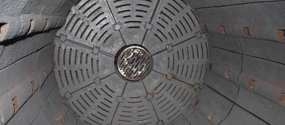
A ball mill liner wear chart records how liner thickness, lifter height, profile shape, or remaining wear material changes over time or operating hours. Maintenance teams use it to compare the current liner condition with the original design condition and the minimum safe replacement limit.
In simple terms, the chart answers four questions:
- How fast is the liner wearing?
- Is wear uniform or localized?
- When should the liner be replaced?
- What operating or material factor is causing the wear pattern?
A liner protects the mill shell while also lifting and cascading grinding media. When the profile becomes too low, too smooth, cracked, or uneven, the grinding charge trajectory changes. That can reduce impact energy, lower throughput, increase power inefficiency, and expose the shell to serious damage.
Regular manual readings, visual inspections, and digital wear scanning can be used to create a reliable wear history. Wear-profile data is also valuable when designing the next liner set for the mill's real operating conditions.
A wear chart may look different from one plant to another, but the core information is usually the same: location, original thickness, measured thickness, wear amount, wear rate, remaining life, and inspection date.
Start with the as-installed liner drawing or inspection report. You need the original thickness or lifter height for every measurement point.
For example:
- Original shell liner thickness: 80 mm
- Current measured thickness: 52 mm
- Material lost: 28 mm
- Minimum allowable thickness: 20 mm
Without an accurate baseline, a wear chart cannot provide an accurate estimate of remaining life.
Expert tip: Record the actual installed dimensions rather than relying only on nominal drawing dimensions. Casting tolerances, liner type, and installation arrangement can cause small differences that become important during wear-life calculations.
Never interpret an individual thickness reading without knowing where it was taken. The shell, feed end, discharge end, lifter face, lifter crest, and grate area experience different loading conditions.
A good chart should identify each reading by:
- Mill zone or compartment
- Clock position
- Axial row number
- Liner plate number
- Measurement point on the plate
- Inspection date or operating hours
For example, a liner at the 3 o'clock position may wear differently from one at the 12 o'clock position because media trajectories, slurry flow, feed distribution, and impact energy are not the same across the mill.
The most basic wear calculation is:
If a liner began at 80 mm and now measures 52 mm:
Material loss alone is useful, but it does not explain whether the current wear is normal. To make maintenance decisions, calculate the wear rate.
The average liner wear rate is commonly expressed as millimeters per 1,000 operating hours:
Wear Rate=Operating HoursOriginal Thickness−Current Thickness×1,000
Using the same example:
- Original thickness: 80 mm
- Current thickness: 52 mm
- Operating time: 8,000 hours
8,00080−52×1,000=3.5 mm per 1,000 hours
This tells the maintenance team that the liner has worn at an average rate of 3.5 mm per 1,000 operating hours.
However, treat this as a starting point—not a guaranteed forecast. Liner wear is rarely perfectly linear. Wear can accelerate after lifter profiles become too low, after ore hardness changes, or when grinding media is oversized or poorly graded.
The most important number is not total wear; it is remaining usable wear allowance.
Remaining Wear Allowance=Current Thickness−Minimum Safe Thickness
If the current thickness is 52 mm and the replacement limit is 20 mm:
52−20=32 mm remaining
At an average rate of 3.5 mm per 1,000 hours, the estimated remaining operating life is:
Remaining Life=3.532×1,000=9,143 hours
This calculation should be reviewed alongside production performance, liner profile condition, bolt integrity, shell inspection requirements, and planned shutdown windows.
| Measurement Item | Example Value | What It Means |
|---|---|---|
| Original liner thickness | 80 mm | As-installed baseline |
| Current liner thickness | 52 mm | Thickness at inspection |
| Minimum safe thickness | 20 mm | Replacement threshold set by engineering review |
| Total material loss | 28 mm | Wear already consumed |
| Operating hours | 8,000 hours | Time since installation |
| Average wear rate | 3.5 mm/1,000 h | Wear speed used for planning |
| Remaining wear allowance | 32 mm | Material available before limit |
| Estimated life remaining | 9,143 hours | Planning estimate, not a guarantee |
Important: Do not use a single average reading to approve continued operation. The thinnest critical point, not the average point, usually controls replacement timing.
A liner wear chart becomes much more valuable when it is paired with a visual inspection. Thickness numbers show how much material has been lost; the wear pattern helps explain why it happened.
Uniform wear is generally a positive sign. It usually indicates that liner design, grinding media, mill speed, ore characteristics, and slurry conditions are reasonably balanced.
Even wear does not mean "no action needed." Track the rate and schedule relining before the minimum thickness is reached.
Accelerated feed-end wear can indicate:
- Coarse feed striking the liner directly
- Poor feed distribution
- High-impact ore
- Incorrect feed-end liner profile
- Oversized grinding balls entering the impact zone
- Insufficient protection in the feed chute or trunnion area
Inspect the feed arrangement, particle-size distribution, ball size mix, and liner design together. Replacing only the worn liner without identifying the cause can lead to repeat failure.
Heavy discharge-end or grate wear may be associated with:
- High slurry velocity
- Inadequate grate opening design
- Oversized pebbles or grinding media
- Pulp-lifter inefficiency
- Recirculating material
- Localized abrasive flow
The discharge end affects mill throughput and classification performance. If this area wears too quickly, the problem may involve the entire discharge system—not only the liner material.
Lifter bars are designed to raise the grinding charge before it cascades or cataracts. As lifters wear down, the charge trajectory changes and grinding efficiency can decline.
Low lifters may contribute to:
- Lower impact breakage
- Media slippage
- Reduced throughput
- Increased power per tonne
- Uneven shell-liner wear
- Changes in product size distribution
Circumferential grooves on worn wave liners can indicate charge slipping and may signal accelerated wear.
These are red-flag conditions. They should trigger an immediate engineering review because they may indicate severe local impact, loose liner components, installation issues, foreign tramp material, or abnormal mill operating conditions.
Look for:
- Missing liner sections
- Cracks around bolt holes
- Loose or broken bolts
- Shell exposure
- Deep localized channels
- Backing material failure
- Unusual noise or vibration
Visible damage, declining grinding efficiency, excess noise, and lower capacity are commonly recognized warning signs that liners may require corrective action or replacement.
No liner material performs the same way in every mill. The wear rate is influenced by the interaction of ore, grinding media, mill design, and operating practice.
Key variables include:
- Ore abrasiveness and hardness
- Feed size and feed distribution
- Ball size, ball hardness, and media charge level
- Mill speed and percentage of critical speed
- Pulp density and slurry flow
- Mill diameter, length, and liner profile
- Liner alloy, hardness, heat treatment, and design
- Grinding circuit classification efficiency
- Operating stability, including start-stop cycles
Industry guidance notes that charge level, mill speed, media condition, and ore feed blend can all affect liner wear life and liner performance. Wear also depends on many interacting factors, including mill dimensions, media and particle size, hardness, speed, mill filling, slurry consistency, and milling time.
At SHANDONG ALLSTAR GRINDING BALL CO., LTD., we encourage customers to evaluate grinding media and liners as one operating system. A change from cast steel balls to forged grinding balls, a different ball-size distribution, or a different hardness range may alter impact intensity and abrasive wear behavior. The right solution requires mill-specific data.
A consistent inspection routine improves the quality of wear-chart data and reduces unexpected shutdown risk.
1. Establish baseline measurements immediately after liner installation.
2. Use fixed reference points so each inspection measures the same locations.
3. Record operating hours and tonnes processed between inspections.
4. Measure liner thickness and lifter height using suitable tools such as ultrasonic thickness gauges, templates, or approved manual methods.
5. Photograph each critical zone under consistent lighting and distance.
6. Record process KPIs, including throughput, power draw, feed size, mill speed, media additions, and cyclone performance.
7. Trend the data rather than relying on a single reading.
8. Set action thresholds for monitoring, ordering replacement liners, and scheduling shutdown work.
Modern liner monitoring may combine manual readings, visual observations, and three-dimensional wear scanning. Regular follow-up measurements can establish both current and historical wear behavior for future liner optimization.
Replacement should not be based only on a fixed number of operating hours. A liner should be replaced when the engineering replacement limit is reached or when its profile can no longer perform its grinding and shell-protection function safely.
Plan a replacement when you observe:
- Thickness near or below the approved minimum limit
- Shell exposure or risk of shell exposure
- Cracked, broken, or loose liner components
- Severely worn lifter height
- Rapidly accelerating wear rate
- Falling throughput or worsening grind size linked to liner condition
- Abnormal vibration, noise, or bolt issues
- A planned shutdown window that offers lower total downtime risk
Do not wait for a liner to fail completely. A planned reline protects safety, mill availability, and the mill shell. Unplanned failures can turn a controlled maintenance event into a long and costly repair.
SHANDONG ALLSTAR GRINDING BALL CO., LTD. is a global manufacturer focused on wear solutions for mineral processing, cement grinding, and power-industry applications. We provide OEM services for overseas brands, wholesalers, and manufacturers.
Our product range includes:
- Forged steel grinding balls
- Cast steel grinding balls
- Grinding mill balls
- Grinding rods
- Grinding cylpebs
For customers reviewing liner wear trends, our technical approach begins with the grinding media. We assess media size, hardness, breakage resistance, application conditions, and compatibility with the grinding circuit. Better media consistency can help stabilize grinding behavior and support more predictable liner wear.
Need support for your grinding-media selection or OEM supply program? Send SHANDONG ALLSTAR your mill size, material type, feed size, ball specification, throughput target, and liner wear records. Our team can help you evaluate a suitable forged or cast grinding-media solution for your operating conditions.
There is no universal normal rate. Wear depends on ore abrasiveness, liner material, mill speed, grinding media, feed size, slurry conditions, and liner design. Compare wear rates with the mill's own historical records and evaluate the thinnest critical points.
Inspection frequency should be risk-based. High-abrasion or high-throughput mills need more frequent checks than stable, low-wear applications. Establish baseline data at installation, then inspect at regular operating-hour or tonnage intervals.
Yes. Subtract the minimum safe thickness from the current thickness, then divide the remaining wear allowance by the measured wear rate. Treat the result as a planning estimate because wear rates can change with operating conditions.
Lifter bars receive high impact from grinding media and are designed to lift the charge. Fast lifter wear may result from high impact energy, oversized balls, high mill speed, aggressive ore, incorrect profile design, or unsuitable material selection.
Include original and current thickness, lifter height, liner location, inspection date, operating hours, tonnes processed, wear rate, photographs, damage notes, mill operating conditions, grinding media details, and recommended action.
Yes. Changes in ball diameter, hardness, breakage resistance, charge level, and size distribution can alter impact and abrasion inside the mill. Review grinding media changes together with liner-wear data and process performance.
No. Visual inspection is important, but it should be combined with repeatable thickness measurements, profile measurements, operating data, and historical wear trends. This produces a more reliable maintenance forecast.
1. [Metso — Mill Liner Wear and Performance Monitoring]
2. [Metso — Correct Liner Selection, Optimal Mill Efficiency]
3. [Metso — Mill Liners]
4. [911Metallurgist — Ball Mill Liner Design]
5. [911Metallurgist — Grinding Media and Liner Wear Rate]
6. [ScienceDirect — Predicting Liner Wear of Ball Mills Using Discrete Element Method]
7. [PatSnap Eureka — Ball Mill Liner Failure Analysis: Root Causes and Corrective Actions]
Hot Tags: China, Global, OEM, private label, manufacturers, factory, suppliers, manufacturing company


